14 ENGLISH
Fig.11: 1. Button 2. Red indicator 3. Battery
cartridge
To remove the battery cartridge, slide it from the tool
while sliding the button on the front of the cartridge.
To install the battery cartridge, align the tongue on the
battery cartridge with the groove in the housing and slip
it into place. Insert it all the way until it locks in place
with a little click. If you can see the red indicator as
Battery protection system
The tool is equipped with a battery protection system.
extend battery life.
The tool will automatically stop during operation if the
tool and/or battery are placed under one of the following
conditions:
Overloaded:
The tool is operated in a manner that causes it to draw
an abnormally high current.
that caused the tool to become overloaded. Then turn
the tool on to restart.
If the tool does not start, the battery is overheated. In
this situation, let the battery cool before turning the tool
on again.
Low battery voltage:
The remaining battery capacity is too low and the tool
will not operate. If you turn the tool on, the motor runs
again but stops soon. In this situation, remove and
recharge the battery.
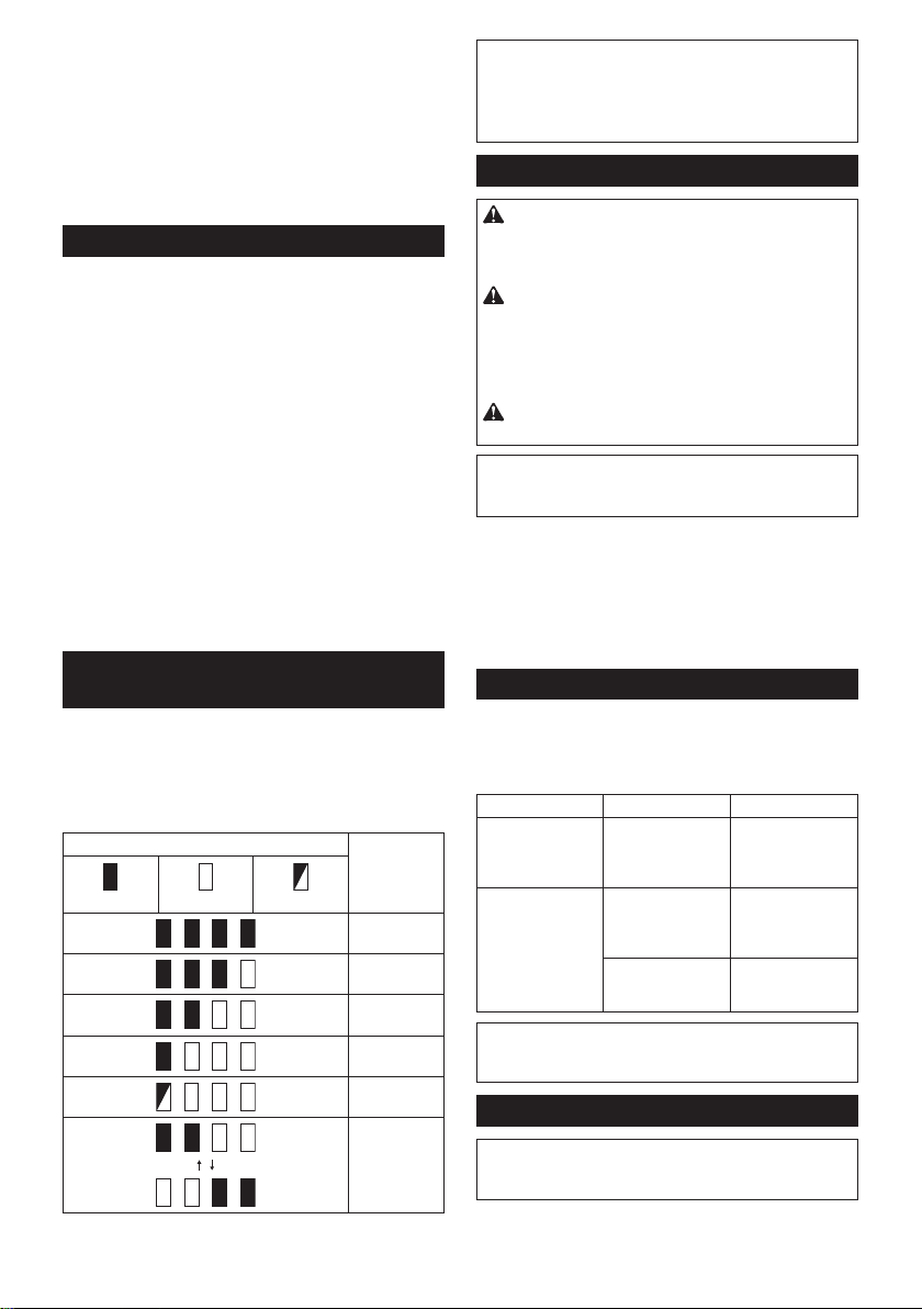
Indicating the remaining battery
capacity
Only for battery cartridges with the indicator
Press the check button on the battery cartridge to indi-
cate the remaining battery capacity. The indicator lamps
light up for a few seconds.
Fig.12: 1. Indicator lamps 2. Check button
Indicator lamps Remaining
capacity
Lighted Blinking
75% to 100%
50% to 75%
25% to 50%
0% to 25%
Charge the
battery.
The battery
may have
malfunctioned.
NOTE: Depending on the conditions of use and the
from the actual capacity.
NOTE:
when the battery protection system works.
Switch action
WARNING: Before installing the battery car-
tridge into the tool, always check to see that the
switch trigger actuates properly and returns to
the "OFF" position when released.
WARNING: For your safety, this tool is
the tool from unintended starting. Never use the
tool if it starts when you pull the switch trigger
Ask your local
Makita Service Center for repairs.
WARNING: Never disable the lock function or
NOTICE: Do not pull the switch trigger forcibly
The switch
may break.
Fig.13: 1.2. Switch trigger
To prevent the switch trigger from being accidentally
switch trigger. Release the switch trigger to stop. The
left side.
Indication lamp
Fig.14: 1. Indication lamp
The indication lamp blinks or lights up when the battery
becomes low or the tool is overloaded. Refer to the
following table for the status and action to be taken.
Indication lamp Status Action to be taken
The lamp blinks
in red.
The remaining
battery is low.
Recharge the
battery, or replace
the battery with a
charged one.
The lamp lights up
in red.
The remaining
battery is empty.
Recharge the
battery, or replace
the battery with a
charged one.
The tool has
stopped due to
overload.
and remove the
cause of overload.
NOTE: The time at which the indication lamp blinks or
lights up varies by the temperature around the work
area and the battery cartridge conditions.
Nylon cutting head
NOTICE: Do not bump the tool to the concrete or
asphalt surface. Bumping to this kind of objects
may cause the tool damage.


Participe da conversa sobre este produto
Aqui você pode compartilhar o que pensa sobre Makita DUR193 Aparador de relva. Se você tiver alguma dúvida, primeiro leia atentamente o manual. A solicitação de manual pode ser feita através do nosso formulário de contato.