¶∂ƒπ√Ã∏ ∞∫ƒπµ∂π∞ ∞¡∞.
∞ÓÙ›ÛÙ·ÛË ÂÈÛfi‰Ô˘ 10 M
¶ÂÚÈÔ¯‹ Û˘¯ÓfiÙËÙ·˜ 40.....400 Hz.
¶ÚÔÛÙ·Û›· ˘ÂÚÊfiÚÙÈÛ˘: ÂÓÂÚÁfi˜ ÙÈÌ‹ AC 600 V
‹ ̤ÁÈÛÙË ÙÈÌ‹ DC 600 V (Û˘Ó¯Ҙ Û fiϘ ÙȘ
ÂÚÈÔ¯¤˜).
ŒÓ‰ÂÈÍË: ¢ÈÔÚıˆÌ¤ÓË Ì¤ÛË ÙÈÌ‹ ·ÓÙÈÛÙÔȯ› ÛÙËÓ
ÂÓÂÚÁfi ÙÈÌ‹ ËÌÈÙÔÓÔÂȉԇ˜ Û¯‹Ì·ÙÔ˜.)
À¶√¢∂π•∏:
1. ∞Ó ‰ÂÓ ÁÓˆÚ›˙ÂÙ ÙËÓ ÂÚÈÔ¯‹ Ù¿Û˘, ı·
Ú¤ÂÈ Ó· ‚¿ÏÂÙ ÙÔÓ ‰È·ÎfiÙË FUNCTION
ÛÙËÓ ·ÓÒÙ·ÙË ÂÚÈÔ¯‹ ̤ÙÚËÛ˘ Î·È Ó·
ÌÂÈÒÛÂÙ ÛÙ·‰È·Î¿ ÙËÓ ÂÚÈÔ¯‹, ·Ó ¯ÚÂÈ·ÛÙ›.
2. ∞Ó ÂÌÊ·ÓÈÛÙ› Ë ¤Ó‰ÂÈÍË “1” ÛÙËÓ ÔıfiÓË, Ë
ÌÂÙÚÔ‡ÌÂÓË ÙÈÌ‹ ‚Ú›ÛÎÂÙ·È ÂÎÙfi˜ Ù˘
Ú˘ıÌÈṲ̂Ó˘ ÂÚÈÔ¯‹˜. √ ‰È·ÎfiÙ˘
FUNCTION ı· Ú¤ÂÈ Ó· Ú˘ıÌÈÛÙ› ÛÂ
˘„ËÏfiÙÂÚË ÂÚÈÔ¯‹.
3. ∏ ̤ÁÈÛÙË Ù¿ÛË ÂÈÛfi‰Ô˘ Â›Ó·È 600 V DC,
ÂÓÂÚÁfi˜ ÙÈÌ‹. ∏ ̤ÙÚËÛË ˘„ËÏfiÙÂÚˆÓ Ù¿ÛˆÓ
‰ÂÓ Â›Ó·È ‰˘Ó·Ù‹.
4. ¶ÚÔÛ¤¯ÂÙ ¿Ú· Ôχ fiÙ·Ó ÌÂÙÚ¿Ù ˘„ËϤ˜
Ù¿ÛÂȘ.
10.3 ª¤ÙÚËÛË Û˘Ó¯ԇ˜ Ú‡̷ÙÔ˜ (ADC)
1. ™˘Ó‰¤ÛÙ ÙÔ ª∞Àƒ√ ηÏÒ‰ÈÔ ÛÙËÓ ˘Ô‰Ô¯‹
COM. ™˘Ó‰¤ÛÙ ÙÔ ∫√∫∫π¡√ ηÏÒ‰ÈÔ ÛÙËÓ
˘Ô‰Ô¯‹ “V mA”.°È· ÌÂÁ¤ıË ÌÂٷ͇ 200mA ηÈ
10A, ·Ê·ÈÚ¤Û·ÙÂ ÙËÓ ∫√∫∫π¡∏ ÎÂÊ·Ï‹ ÛÙËÓ
«10A» Ú›˙· ·ÚÔ¯‹˜.
2. µ¿ÏÙ ÙÔÓ ‰È·ÎfiÙË FUNCTION ÛÙËÓ
ÂÈı˘ÌËÙ‹ Ú‡ıÌÈÛË “A” Î·È Û˘Ó‰¤ÛÙ ٷ
ηÏ҉ȷ Û ÛÂÈÚ¿ Ì ÙÔ Î‡Îψ̷ Ô˘ ı¤ÏÂÙ ӷ
ÌÂÙÚ‹ÛÂÙÂ. ¶ÚÔÛ¤ÍÙ ÙË ÛˆÛÙ‹ ÔÏÈÎfiÙËÙ·
(ÎfiÎÎÈÓÔ Â›Ó·È + Î·È Ì·‡ÚÔ Â›Ó·È -), ‰È·ÊÔÚÂÙÈο
Ë ÔıfiÓË ı· ‰Â›¯ÓÂÈ ÙÔ Û‡Ì‚ÔÏÔ ÏËÓ (-) ÚÈÓ
·fi ÙËÓ ÙÈÌ‹. ∏ Ù¯ÓÈ΋ ηÙ‡ı˘ÓÛË Ú‡̷ÙÔ˜
ÙÔ˘ ∫√∫∫π¡√À ηψ‰›Ô˘ ÚÔ˜ ÙÔ ª∞Àƒ√
ηÏÒ‰ÈÔ ÂÌÊ·Ó›˙ÂÙ·È Ù·˘Ùfi¯ÚÔÓ· Ì ÙËÓ ÈÛ¯‡
ÙÔ˘ Ú‡̷ÙÔ˜.
3. ¢È·‚¿ÛÙ ÙËÓ ÙÈÌ‹ Û (milli-) Ampere.
¶∂ƒπ√Ã∏ ∞∫ƒπµ∂π∞ ∞¡∞.
∞ÛÊ¿ÏÂÈ· ˘ÂÚÊfiÚÙÈÛ˘: ·ÛÊ¿ÏÂÈ· 0.2 A/250-V, Ë
ÂÚÈÔ¯‹ 10 A ‰ÂÓ ÚÔÛٷهÂÙ·È.
À¶√¢∂π•∏:
1. ∞Ó ‰ÂÓ ÁÓˆÚ›˙ÂÙ ÙËÓ ÂÚÈÔ¯‹ Ú‡̷ÙÔ˜, ı·
Ú¤ÂÈ Ó· ‚¿ÏÂÙ ÙÔÓ ‰È·ÎfiÙË FUNCTION
ÛÙËÓ ·ÓÒÙ·ÙË ÂÚÈÔ¯‹ ̤ÙÚËÛ˘ Î·È Ó·
ÌÂÈÒÛÂÙ ÛÙ·‰È·Î¿ ÙËÓ ÂÚÈÔ¯‹ ̤ÙÚËÛ˘, ·Ó
¯ÚÂÈ·ÛÙ›.
2. ∞Ó ÂÌÊ·ÓÈÛÙ› Ë ¤Ó‰ÂÈÍË “1” ÛÙËÓ ÔıfiÓË, Ë
ÌÂÙÚÔ‡ÌÂÓË ÙÈÌ‹ ‚Ú›ÛÎÂÙ·È ÂÎÙfi˜ Ù˘
Ú˘ıÌÈṲ̂Ó˘ ÂÚÈÔ¯‹˜ ̤ÙÚËÛ˘. √
‰È·ÎfiÙ˘ FUNCTION ı· Ú¤ÂÈ Ó· Ú˘ıÌÈÛÙ›
Û ˘„ËÏfiÙÂÚË ÂÚÈÔ¯‹ ̤ÙÚËÛ˘.
3. ∏ ÂÚÈÔ¯‹ 10A ‰ÂÓ ÚÔÛٷهÂÙ·È ÌÂ
·ÛÊ¿ÏÂÈ·. °È· ÙÔÓ ÏfiÁÔ ·˘Ùfi, ÌËÓ
Ú·ÁÌ·ÙÔÔț٠̤ÙÚËÛË ÁÈ· ÂÚÈÛÛfiÙÂÚ·
·fi 10 ‰Â˘ÙÂÚfiÏÂÙ·.
10.4 ª¤ÙÚËÛË Ù˘ ·ÓÙ›ÛÙ·Û˘ ( Ohm)
1. ™˘Ó‰¤ÛÙ ÙÔ ª∞Àƒ√ ηÏÒ‰ÈÔ ÛÙËÓ ˘Ô‰Ô¯‹
“COM” Î·È ÙÔ ∫√∫∫π¡√ ηÏÒ‰ÈÔ ÛÙËÓ
˘Ô‰Ô¯‹ “V mA”. (Àfi‰ÂÈÍË: ∏ ÔÏÈÎfiÙËÙ· ÙÔ˘
ÎfiÎÎÈÓÔ˘ ηψ‰›Ô˘ Â›Ó·È “+”.)
2. ƒ˘ıÌ›ÛÙ ÙÔÓ ‰È·ÎfiÙË FUNCTION ÛÙËÓ
ÂÈı˘ÌËÙ‹ ÂÚÈÔ¯‹ ̤ÙÚËÛ˘ “ ”.
¶∂ƒπ√Ã∏ ∞∫ƒπµ∂π∞ ∞¡∞.
∞ÛÊ¿ÏÂÈ· ˘ÂÚÊfiÚÙÈÛ˘: ÂÓÂÚÁfi˜ ÙÈÌ‹ 250 V DC
‹ AC, ÁÈ· ÙÔ Ôχ 15 ‰Â˘ÙÂÚfiÏÂÙ·
3. ™˘Ó‰¤ÛÙ ÙȘ ·Î›‰Â˜ ̤ÙÚËÛ˘ ÛÙÔ ÛÙÔȯ›Ô
Ô˘ ı¤ÏÂÙ ӷ ÌÂÙÚ‹ÛÂÙÂ. µÂ‚·Èˆı›Ù fiÙÈ ÙÔ
ÛÙÔÈ¯Â›Ô ‰ÂÓ Â›Ó·È Û˘Ó‰Â‰Â̤ÓÔ Ì ٷ ¿ÏÏ·
ÛÙÔȯ›·. ªËÓ ·ÁÁ›˙ÂÙ ÙȘ ·Î›‰Â˜ ̤ÙÚËÛ˘ ÁÈ·
Ó· ÌËÓ ÂËÚ¿ÛÂÙ ÙȘ ÙÈ̤˜ Ù˘ ·ÓÙ›ÛÙ·Û˘.
4. ¢È·‚¿ÛÙ ÙË ÌÂÙÚÔ‡ÌÂÓË ÙÈÌ‹ Û (Ohm).
5. ∫·Ù¿ ÙË Ì¤ÙÚËÛË ·ÓÙÈÛÙ¿ÛÂˆÓ Î·Ù·Ó·ÏÒÓÂÙ·È
Ú‡̷ ·fi ÙËÓ ÂÛˆÙÂÚÈ΋ Ì·Ù·Ú›·. ∏
ηٷӿψÛË Ú‡̷ÙÔ˜ ı· ÔÈΛÏÏÂÈ ·Ó¿ÏÔÁ·
Ì ÙËÓ ÂÈÏÂÁ̤ÓË ÂÚÈÔ¯‹ ÌÂÙÚ‹ÛˆÓ.
À¶√¢∂π•∏:
1. ∞Ó Ë ÌÂÙÚÔ‡ÌÂÓË ÙÈÌ‹ ÍÂÂÚÓ¿ ÙËÓ ·ÓÒÙ·ÙË
ÙÈÌ‹ Ù˘ ÂÈÏÂÁ̤Ó˘ ÂÚÈÔ¯‹˜ ÌÂÙÚ‹ÛˆÓ, Ë
ÔıfiÓË ı· ‰Â›ÍÂÈ “1”. ∂ÈϤÍÙ ÌÈ· ˘„ËÏfiÙÂÚË
ÂÚÈÔ¯‹ ÌÂÙÚ‹ÛˆÓ. ∞Ó Ë ·ÓÙ›ÛÙ·ÛË Â›Ó·È
ÂÚ›Ô˘ 1 ª ‹ ˘„ËÏfiÙÂÚË, Ë Û˘Û΢‹
̤ÙÚËÛ˘ ÂÓ‰¤¯ÂÙ·È Ó· ¯ÚÂÈ·ÛÙ› Ï›Á·
‰Â˘ÙÂÚfiÏÂÙ· ÁÈ· Ó· ÛÙ·ıÂÚÔÔÈËı›. ∞˘Ùfi
Â›Ó·È Ê˘ÛÈÔÏÔÁÈÎfi fiÙ·Ó ÌÂÙÚÔ‡ÓÙ·È ˘„ËϤ˜
·ÓÙÈÛÙ¿ÛÂȘ.
2. ∞Ó Ë Â›ÛÔ‰Ô˜ ‰ÂÓ Â›Ó·È Û˘Ó‰Â‰Â̤ÓË, .¯. ÛÂ
‰È·ÎÂÎÔÌ̤ÓÔ Î‡Îψ̷, Ë ÔıfiÓË ı· ‰Â›¯ÓÂÈ ÙÔÓ
·ÚÈıÌfi “1”. ∞˘Ùfi ÛËÌ·›ÓÂÈ fiÙÈ Ë Ì¤ÙÚËÛË
‚Ú›ÛÎÂÙ·È ÂÎÙfi˜ Ù˘ ÂÈϯı›۷˜ ÂÚÈÔ¯‹˜.
80 Ferm
HINT:
1. In case the voltage range is unknown, you must
put the FUNCTION switch in the highest
measurement range and then reduce the range
gradually if required.
2. If the figure "1" now appears on the display, the
measurand lies outside the range set. The
FUNCTION switch must be switched to a higher
range.
3. The maximum input voltage is 600 V DC. Higher
voltages cannot be measured.
4. Proceed extremely cautiously with the
measurement of high voltages.
10.2 Measuring alternating voltage (V AC)
1. Connect the BLACK lead to the "COM"
connecting point and the RED lead to the
"V mA" connecting point.
2. Set the FUNCTION switch on the desired "V"
setting and connect the leads to the voltage
source to be measured or measuring points. The
polarity of the measuring tips is not relevant.
3. Read off the measured value in Volt.
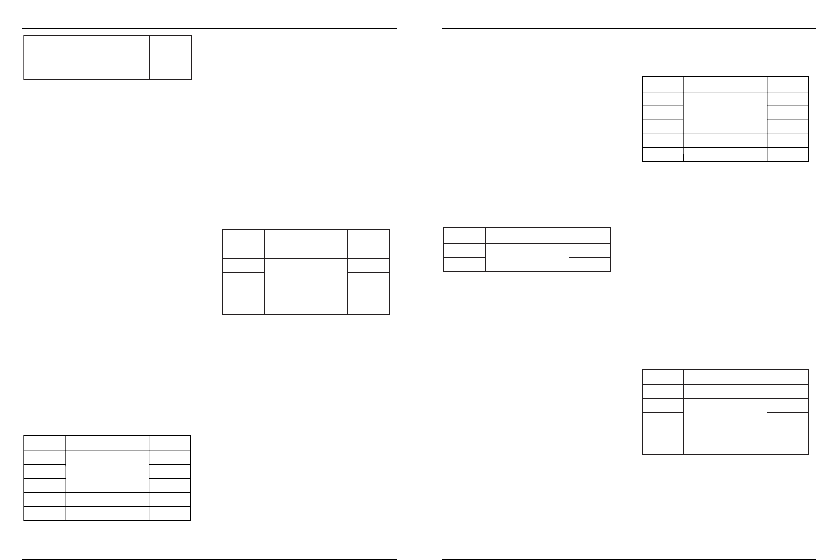
RANGE ACCURACY RES.
Input resistance 10 M
Frequency range 40.....400 Hz.
Overload protection AC 600 V Effective value or DC
600 V peak value (constantly in all ranges).
Display:Corrected centre point corresponds to the
effective value in a sinusoidal form.)
HINT:
1. In case the voltage range is unknown, you must
set the FUNCTION switch in the highest
measurement range and then reduce the range
gradually if required.
2. If the figure "1" now appears on the display, the
measurand lies outside the range set. The
FUNCTION switch must be switched to a higher
range.
3. The maximum input voltage is 600 V AC
effective value. Higher voltages cannot be
measured.
4. Proceed extremely cautiously with the
measurement of high voltages.
10.3 Measuring direct current (ADC)
1. Connect the BLACK lead to the COM connector
socket. Connect the RED lead to the "V mA"
connector socket. For measurements between
200mA and 10A, remove RED lead to “10A”
connector socket.
2. Set the FUNCTION switch on the desired "A"
setting and connect the leads in series to the
power circuit to be measured. Observe correct
polarity (red is + and black is -), otherwise the
display shows a minus sign before the value.
The technical current direction of the RED lead
to the BLACK lead is displayed at the same time
with the current strength.
3. Read off the value in (milli-) Ampere.
RANGE ACCURACY RES.
Overload protection 0.2 A/250-V cut-out, 10-A-
range not protected.
HINT:
1. In case the current range is previously unknown,
you must set the FUNCTION switch in the
highest measurement range and then reduce
the measurement range gradually if required.
2. If the figure "1" now appears on the display, the
measurand lies outside the set measurement
range. The FUNCTION switch must be switched
to a higher measurement range.
3. The 10A range is not protected with a fuse. Do
not, therefore, measure for longer than 10
seconds.
10.4 Measuring the resistance ( Ohm)
1. Connect the BLACK lead to the "COM"
connector socket and the RED lead to the
"V mA" connector socket. (Hint: The polarity of
the red lead is then "+".)
2. Set the FUNCTION switch on the desired " "
measuring range.
RANGE ACCURACY RES.
Overload protection 250 V DC or AC Effective
value, for maximum 15 seconds
3. Connect the measuring tips to the components
to be measured. Ensure that the component is
not linked to the other components. Do not touch
the measuring tips so as not to affect resistance
values.
4. Read off the measured value in (Ohm).


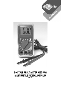
Participe da conversa sobre este produto
Aqui você pode compartilhar o que pensa sobre FERM MMM1007 Multímetro. Se você tiver alguma dúvida, primeiro leia atentamente o manual. A solicitação de manual pode ser feita através do nosso formulário de contato.
responder | Isso foi útil (0) (Traduzido pelo Google)